


What is FOD?
FOD stands for Foreign Object Detection, which is the abbreviation of Foreign Object Detection in English. It is a technical detection method to avoid an excessive temperature rise of the system caused by accidental objects during the wireless charging process.
Wireless charging is different from wired charging. The latter can only work after being physically hard-connected, while wireless charging connects two independent objects through a magnetic field, so there may be foreign objects in the path. Suppose the foreign body is a conductor such as a metal. In that case, it will inevitably generate an induced electromotive force in the alternating magnetic field, forming an induced current inside the conductor. The metal is equivalent to a resistance, which generates high heat and causes harm.
Therefore, FOD technology is essential and very important in wireless charging applications. For example:
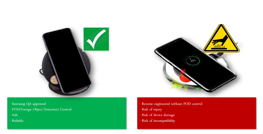
In the picture on the left, the charging transmitter (Transmitter, hereinafter referred to as TX) has the FOD function. When a coin is placed, the TX passes the FOD detection, judges a foreign object, and exits the charging mode.
In the picture on the right, TX does not have the FOD function. When a coin is placed, TX will not stop emitting a magnetic field due to the presence of foreign objects. The coin generates eddy current heating in the alternating magnetic field continuously established by TX, which can easily cause accidents.
Several detection methods of FOD
There are many ways to detect foreign objects; for example, power loss and Q value can be detected.
In the Qi protocol, only the temperature rise of the receiver (Receiver, hereinafter referred to as RX) in wireless charging is specified. The test in the certification laboratory stipulates that the temperature rise of RX shall not exceed 12°C of the ambient temperature. However, it does not specify which method must be used to achieve it. The current general schemes are listed in the following table:
| Protocols | Methods |
| BPP | Power Loss, A Power Receiver shall report its Received Power Received in a Received Power Packet (0x04) such that Receiver – 350 mW ≤ PR ≤ Received(in Power Transfer phase) |
| EPP | Step 1: Measure Q Factor to Ensure no FO Present. (in negotiation phase)
Step 2: Calibration Transmitted and Received. (in negotiation phase) Step 3: Power Loss: ΡPT-ΡPR≤Limit ΔΡ.(in Power Transfer phase) |
What is Power Loss detection?
PLOSS: 300 mW is an appropriate threshold value for limiting heating of Foreign Objects
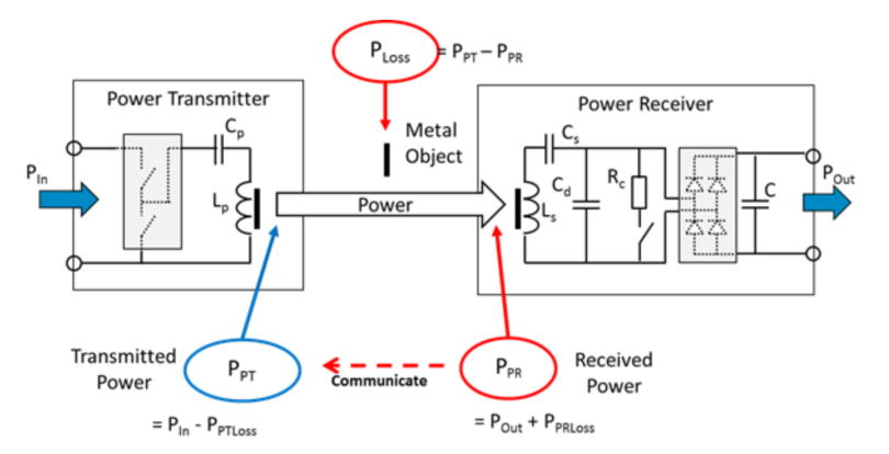
As shown in the figure, TX judges whether FOD occurs by calculating PLOSS, PLLOSS =PPT-PPR.
among them:
PPT = PIN-PPTLOSS, the PIN is equal to the input power, PPTLOSS is all the necessary transmission loss power at the TX end, including but not limited to the equivalent impedance of the primary coil and capacitor, the power consumption generated by the inverter circuit, and PCB traces, and the metal at the TX end Eddy current loss and system power consumption generated by the device.
PPR = POUT + PPRLOSS, POUT is equal to the output power, PPRLOSS is all the necessary transmission loss power at the RX end, including but not limited to the equivalent impedance of the secondary coil and capacitor, the power consumption generated by the rectifier circuit and PCB traces, and the metal at the RX end Eddy current loss and system power consumption generated by the device.
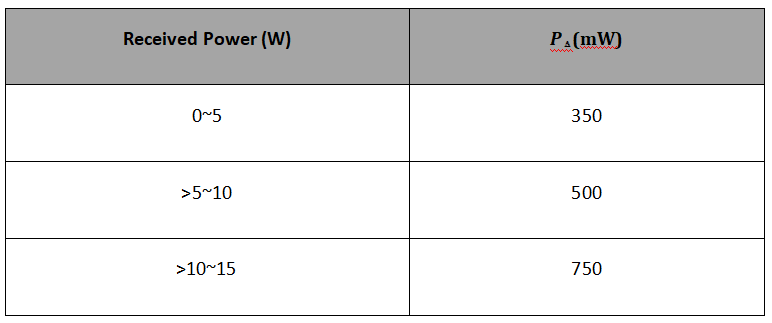
The power loss method is used to detect the presence of foreign objects, and its reliability mainly depends on whether the power reported by TX and RX is accurate. Taking into account some unmeasurable factors, such as the degree of freedom, the power reported by TX and RX under different loads has an offset, and the energy is partly dispersed into the air. In order to prevent TX from falsely reporting FOD, usually Perceived = PPR + PΔ reported on the RX side, Among them, PΔ is used as compensation for the aforementioned factors.
This shows that when there is no foreign matter on the TX surface, the power reported by RX is always equal to or greater than the transmission power PPT of TX. Depending on the output power, PΔ is also different. Its value is generally 5% of the maximum output power. The recommended PΔ value in Qi is as follows:
The advantage of this scheme is that it can detect FOD in real-time during power transmission, but it also has disadvantages. Since PPT and PPR are estimated by TX and RX, respectively, there may be systematic deviations even in the absence of foreign objects, which will affect the accuracy of TX FOD.
For example, when there is no foreign object, the transmit power PPT calculated at the TX end is 5W under ideal circumstances. The received power PPR calculated at the RX end is also equal to 5W. However, due to detection and estimation errors, the actual PPT at the TX end is 5.1W (or 4.9W). ), the actual PPR of the RX end is equal to 4.9W (or 5.1W), then the PLOSS is biased from the standard 0 to 200mW (-200mW), and the original margin of 300mW becomes 100mW (500mW), which reduces the tolerance threshold of the system. At this time, if TX relaxes its threshold, it will cause insensitive detection of foreign objects, and false detection of the shrinkage threshold may occur.
Power calibration
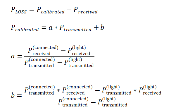
In order to improve the effectiveness of the power loss detection method, the TX end can use the power correction method to solve the system deviation problem. Still, the premise of the power correction is that there is no foreign matter on the TX surface. This problem can be determined by the Q value detection in the next section to determine whether there is foreign matter.
According to the introduction in the previous section, the system deviation is related to the transmission power level. Ideally, it should be calibrated in sections within the full range of the output power. However, because this method is not easy to implement, a compromise solution is adopted: In the calibration stage, TX And RX will determine their own output and received power according to “light” load and “connected” load. Based on these two load states, TX can use the following linear interpolation method to calibrate the output or received power.
Q value detection
The Q value is the main parameter to measure the inductance device. It refers to the ratio of the inductance to the equivalent loss resistance when the inductor works under a certain frequency of AC voltage. The higher the Q value, the smaller the inductor loss. The Q value of the TX coil will be affected by the external environment. For example, when there are other metals on the surface, the inductance of the TX coil will decrease, and the equivalent impedance will increase so that the Q value will decrease.
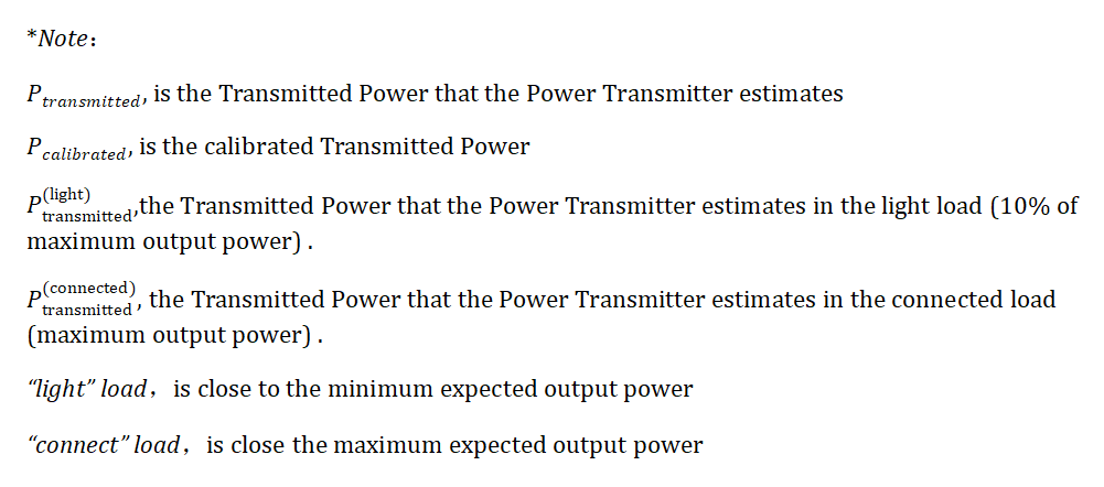
Qi’s EPP protocol stipulates that TX must include a Q value detection function in the negotiation phase to determine whether there are foreign objects on the surface. In order to ensure that TX can correctly determine whether the Q value is reduced due to the RX coil or a foreign object, RX should provide a reference Q value to TX through the 0x22 package. TX will then determine a reasonable Q value margin based on this value, and finally Compare the actual measured value to determine whether there is a foreign body.
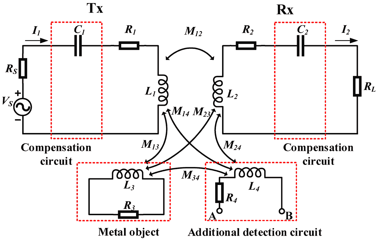
There are many ways to detect the Q value. Qi provides a measurement scheme but does not limit it. The following figure shows the reference scheme of Qi. As shown in the figure, the left side is the schematic diagram of the detection circuit. In addition to the coil, it also includes a sinusoidal voltage source and a resonant capacitor. When choosing the resonant capacitor, the reasonable working range of the circuit should be combined, and the resonant frequency should be determined before choosing. In this example, the resonance frequency is 100kHz, and the Q value of the coil is equal to the ratio of the effective voltage value of the two ends of the coil to the effective voltage value of the driving power supply, that is, Q=V2/V1.

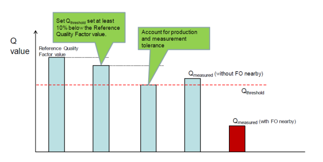
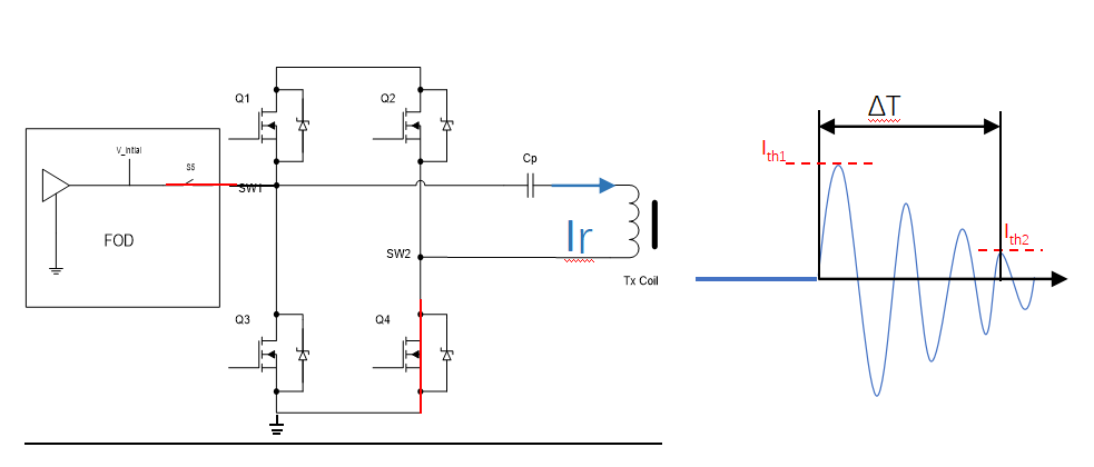
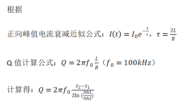
The figure below is a Q value detection scheme adopted by Volta for reference. When the Q value is detected, the oscillating circuit is precharged first. That is, the S5 and Q4 tubes are turned on at the same time. When the voltage reaches the preset value Initial, S5 is turned off, and Q3 is turned on. At this time, the current in the capacitor and inductance circuit will oscillate and gradually decay to 0. Whether the foreign matter will cause the current decay time to change, take the fixed thresholds Ith1 and Ith2 and measure ΔT to calculate the Q value.
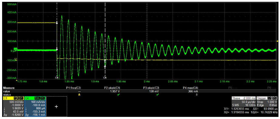
Without FOD 50us/div
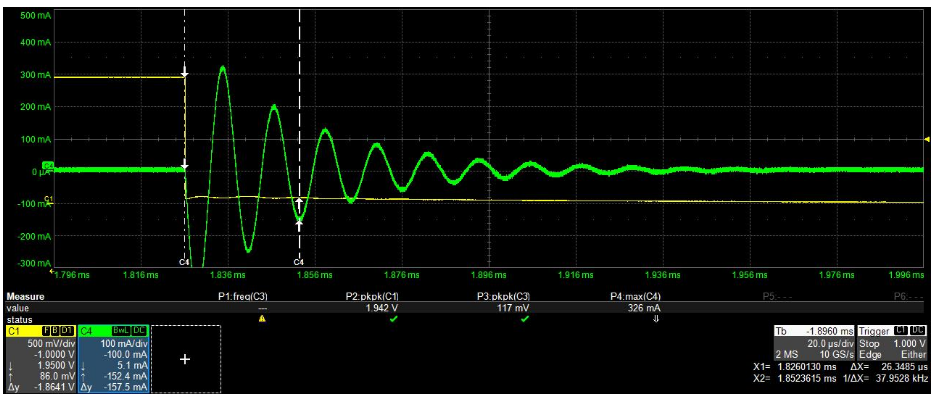
With FOD 20us/div
Conclusion
I hope this article will be helpful to engineers engaged in charging design and help everyone to perform FOD inspections more accurately and efficiently so that the products designed can make users more at ease.