

The first question in a car-charger enquiry is often “How many watts?” In a vehicle, that number is only useful when the charger can maintain stable operation in the actual console, with a moving phone, elevated cabin temperature and an electrical supply that is not as quiet as a laboratory adapter.
Good in cabin wireless charging design begins with the vehicle environment and the user’s phone position. The TX electronics, coil, cradle, input protection, thermal strategy and mechanical retention must be developed as one assembly.
Define the product level
There is a large difference between an aftermarket vent-mount charger and an embedded console module supplied into an automotive program. The required input protection, validation, documentation, component controls and lifecycle support will differ.
The project brief should state:
- Aftermarket accessory or vehicle-integrated module
- 12V, 24V or regulated intermediate input
- Target devices and charging profile
- Mounting location and available airflow
- Cabin and storage-temperature requirements
- Vehicle interfaces, indicators and diagnostics
- Required standards, approvals and customer-specific tests
- Expected production life and change-notification rules
Without those inputs, a board can be electrically functional and still be unsuitable for the vehicle program.
Control phone position during motion
On a desk, the user can reposition a phone when charging is slow. In a car, braking, cornering and road vibration move the device. A flat console tray needs friction, geometry or magnetic alignment that keeps the receiver inside the validated charging window.
Evaluate different phone sizes, camera bumps and common cases. A tall phone may bridge over a cradle feature and increase tilt. A thick case raises the Z-gap. Loose objects can push the phone away from coil center.
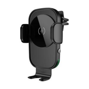
For a clamping charger, measure how the mechanism locates the coil after repeated cycles. Gear wear, spring force and arm tolerance can change the final position. The clamp must hold the phone without operating buttons or interfering with normal removal.
Design for cabin heat
The vehicle may sit in sunlight before charging begins. At a high starting temperature, the phone and charger can reduce power earlier than they do in a room-temperature demonstration.
Test the complete assembly at defined cabin conditions. Monitor the TX coil, switching devices, resonant components, input connector and accessible surfaces. Record power over time, because a short successful peak does not describe sustained performance.
The console structure is part of the thermal path. Foam, carpet, storage bins and nearby electronics can trap heat. A metal bracket may spread heat but also influence the magnetic field and FOD, so the two effects must be assessed together.
Protect the vehicle input
A vehicle supply can experience reverse connection, cranking-related voltage changes and transient events. The protection strategy depends on where the module connects and what conditioning already exists upstream.
Define the input range, surge and reverse requirements with the vehicle customer. Check connector and cable voltage drop at full load. The charger should enter a controlled state when the input is insufficient rather than cycling rapidly.
For an aftermarket product powered through a USB adapter, the adapter and cable remain part of the system. Qualify the intended combination and describe the minimum input requirement to the buyer.
Treat FOD as a console-level function
Coins, keys and metal accessories are foreseeable objects in a vehicle console. Foreign object detection must be evaluated with the final coil, ferrite, magnets, housing and nearby structure.
Test objects at multiple positions, including edges and partial overlap. Also verify normal phones with cases and magnetic accessories. The objective is not only to trip on test objects; it is to avoid false shutdowns during valid use.
If a console surface material, magnet or metal support changes, repeat the affected FOD and thermal work. A cosmetic engineering change can alter the transmitter’s loss model.
Plan EMC with the vehicle system
Wireless charging uses switching power electronics and a magnetic field near key fobs, antennas, displays, audio systems and other vehicle electronics. Early pre-compliance testing is less expensive than shielding a completed console.
Use production-like cables, grounding and mounting. Evaluate different charging states, receiver positions and fault recovery. Cable routing can make a bench-clean module behave differently once installed.
The WPC states that Qi Certified car chargers are tested for compatibility and non-interference with other car electronics within the Qi certification program. Product teams should still confirm the correct certification and vehicle-level requirements for their own design and market.
Validate user behavior, not only laboratory alignment
Create a test matrix that includes:
- Small and large phones
- Different receiver-coil positions
- Thin, thick and magnetic cases
- Portrait and landscape orientation where supported
- Vibration and repeated road movement
- Cold start and hot-cabin start
- Low and high battery state
- Phone operation during charging
- Foreign objects and loose console items
Record charging initiation, interruptions, temperature, sustained performance and indications. If the system intentionally reduces power, the user indication and product claim should remain honest.
Build automotive discipline into production
For every unit, control coil location, ferrite, magnet polarity, firmware and critical components. End-of-line testing should verify charging in the defined fixture position and any required communication or diagnostic output.
Maintain traceability to PCBA lot, coil lot and software revision. Agree on change notification for controllers, MOSFETs, capacitors, coils, ferrite, magnets and key mechanical materials. A functionally similar substitute may not be magnetically or thermally equivalent.
Choosing a starting platform
An existing TX module can shorten early feasibility work, but it must be reviewed against the vehicle input, console stack and program requirements. A finished aftermarket product follows a different development path from an embedded automotive-grade module.
CowinLink’s wireless charging application page outlines automotive use cases, while our finished wireless car chargers and custom engineering workflow provide different starting points.
In cabin wireless charging design: factory conclusion
The practical factory view is that vehicle performance comes from margin. Design enough alignment, thermal and electrical margin for real cabin conditions, then protect that margin with controlled materials and production tests. That matters more than the best wattage number recorded on an open bench. A robust in cabin wireless charging design is proven in the console, at temperature and under motion.